- 您现在的位置:买卖IC网 > Sheet目录17365 > GBA32DTKD (Sullins Connector Solutions)CONN EDGECARD 64POS DIP .125 SLD
Sullins Edgecards
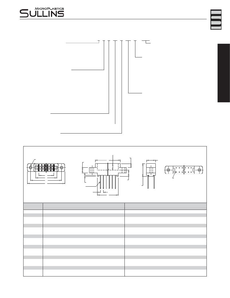
.125” [3.18 mm] Contact Centers, .610” [15.49 mm] Insulator Height
Dip Solder/Wire Wrap/Right Angle
PART NUMBER CODING
MATERIALS (Insulator/Contact)
E = PBT/Phosphor Bronze (Standard)
R = PPS/Phosphor Bronze
G = PA9T/Phosphor Bronze
A = PPS/Beryllium Copper
E B A 50 D CM H - Sxxx
MODIFICATION CODE (Consult Factory)
OMIT FOR STANDARD
-S288 = Card Extender Accepts .062”[1.57] PCB
MOUNTING STYLE (Opposite Page)
J = PA9T/Beryllium Copper
(Consult Factory for Other Materials)
CONTACT FINISH - RoHS Compliant
All platings are Lead Free and have .000050” Nickel underplate
Contact Surface Termination
B = .000010” Gold .000100” Pure Tin, Matte
H
I
S
N
W
D
X
=
=
=
=
=
=
=
Clearance Holes
Threaded Inserts
Side Mounting
No Mounting
Flush Mounting
Flush Mounting
Flush Mounting with Threaded Inserts
C
=
.000030” Gold
.000100” Pure Tin, Matte
T
=
Flush Mounting with Threaded Inserts
G
=
.000010” Gold
.000005” Gold
Y =
S =
M =
E =
.000030” Gold
Contact Surface
.000010” Gold
.000030” Gold
.000100” Pure Tin, Matte
.000005” Gold
Overall Plating
.000010” Gold
.000010” Gold
.000100” Pure Tin, Matte
TERMINATION TYPE (Opposite Page)
Hairpin Bellows **
CS = .025” [.64mm] Square Dip Solder
CM = .025 [.64mm] Square Wire Wrap
CA, CB, CC = .025” [.64mm] Square Right Angle
CW, CT = .015” x .025” [.38 x .64] Dip Solder
CONTACT CENTERS
A = .125” [3.18mm]
NUMBER OF CONTACT POSITIONS
See Chart Below
READOUT (Opposite Page)
D = Dual
H = Half Loaded
DIMENSIONS Dimensions in [ ] are in millimeters, all others are in inches.
.297 [7.54] INSERTION DEPTH
Loop Bellows
RS = .025” [0.64mm] Square Dip Solder
CK, TK = .026” [0.66mm] Round Dip Solder
RM = .025” [0.64mm] Square Wire Wrap
TA, TB, TM = .025” [.64mm] Square Right Angle
**Available with B or C plating and Phosphor Bronze Only
REFER TO MOUNTING STYLE
.250
[6.35]
C
.180 [4.57]
.370 [9.40]
1
2
3
4
5
6
95 97 99
96 98 100
A
B
D
E
REFER TO TERMINATION TYPE
.060
[1.52]
.313
[7.95]
.610
[15.49]
CONTACT MARKINGS
1 3 5 . . . 95 97 99
2 4 6 . . . 96 98 100
.125 [3.18] TYP.
F
Tolerances with PPS Insulator Material may vary slightly due to shrinkage differential; Consult Factory.
POSITIONS/
INCHES
[MILLIMETERS]
CONTACTS
A±.008 B±.008
C±.015 D±.010
E±.020
F±.015
A±0.20
B±0.20
C±0.38 D±0.25
E±0.51
F±0.38
06/12 0.625 0.875
10/20 1.125 1.375
14/28 1.625 1.875
15/30 1.750 2.000
18/36 2.125 2.375
22/44 2.625 2.875
24/48 2.875 3.125
25/50* 3.000 3.250
28/56 3.375 3.625
30/60 3.625 3.875
31/62 3.750 4.000
32/64 3.875 4.125
35/70 4.250 4.500
36/72 4.375 4.625
40/80 4.875 5.125
43/86 5.250 5.500
44/88 5.375 5.625
49/98 6.000 6.250
50/100 6.125 6.375
1.035 1.295
1.535 1.795
2.035 2.295
2.160 2.420
2.535 2.795
3.035 3.295
3.285 3.545
3.410 3.670
3.785 4.045
4.035 4.295
4.160 4.420
4.285 4.545
4.660 4.920
4.785 5.045
5.285 5.545
5.660 5.920
5.785 6.045
6.410 6.670
6.535 6.795
1.555
2.055
2.555
2.680
3.055
3.555
3.805
3.930
4.305
4.555
4.680
4.805
5.180
5.305
5.805
6.180
6.305
6.930
7.055
0.875
1.375
1.875
2.000
2.375
2.875
3.125
3.250
3.625
3.875
4.000
4.125
4.500
4.625
5.125
5.500
5.625
6.250
6.375
15.88
28.58
41.28
44.45
53.98
66.68
73.03
76.20
85.73
92.08
95.25
98.43
107.95
111.13
123.83
133.35
136.53
152.40
155.58
22.23
34.93
47.63
50.80
60.33
73.03
79.38
82.55
92.08
98.43
101.60
104.78
114.30
117.48
130.18
139.70
142.88
158.75
161.93
26.29 32.89
38.99 45.59
51.69 58.29
54.86 61.47
64.39 70.99
77.09 83.69
83.44 90.04
86.61 93.22
96.14 102.74
102.49 109.09
105.66 112.27
108.84 115.44
118.36 124.97
121.54 128.14
134.24 140.84
143.76 150.37
146.94 153.54
162.81 169.42
165.99 172.59
39.50
52.20
64.90
68.07
77.60
90.30
96.65
99.82
109.35
115.70
118.87
122.05
131.57
134.75
147.45
156.97
160.15
176.02
179.20
22.23
34.93
47.63
50.80
60.33
73.03
79.38
82.55
92.08
98.43
101.60
104.78
114.30
117.48
130.18
139.70
142.88
158.75
161.93
* Consult factory for availability.
www.sullinscorp.com | 760-744-0125 | toll-free 888-774-3100 | fax 760-744-6081 | info@sullinscorp.com
51
发布紧急采购,3分钟左右您将得到回复。
相关PDF资料
695D104X0050A2T
CAP TANT 0.1UF 50V 20% 1305
GBM22DRST
CONN EDGECARD 44POS DIP .156 SLD
L-05B12NJV6T
IND CER RF 12NH 0201
GCA24DTBN
CONN EDGECARD 48POS R/A .125 SLD
GBM31DRSN
CONN EDGECARD 62POS DIP .156 SLD
A9BBA-0708E
FLEX CABLE - AFJ07A/AE07/AFJ07A
GBM31DRSH
CONN EDGECARD 62POS DIP .156 SLD
A9BBG-1102F
FLEX CABLE - AFF11G/AF11/AFF11G
相关代理商/技术参数
GBA32DTKD-S288
功能描述:CONN EDGECARD 64POS .125 EXTEND RoHS:是 类别:连接器,互连式 >> Card Edge 系列:- 标准包装:1 系列:- 卡类型:非指定 - 双边 类型:母头 Number of Positions/Bay/Row:44 位置数:88 卡厚度:0.062"(1.57mm) 行数:2 间距:0.100"(2.54mm) 特点:- 安装类型:通孔 端子:焊接 触点材料:磷青铜 触点表面涂层:锡 触点涂层厚度:100µin(2.54µm) 触点类型::全波纹管 颜色:蓝 包装:管件 法兰特点:- 材料 - 绝缘体:聚对苯二甲酸丁二酯(PBT) 工作温度:-65°C ~ 125°C 读数:双
GBA32DTKH
功能描述:CONN EDGECARD 64POS DIP .125 SLD RoHS:是 类别:连接器,互连式 >> Card Edge 系列:- 标准包装:1 系列:- 卡类型:非指定 - 双边 类型:母头 Number of Positions/Bay/Row:6 位置数:12 卡厚度:0.062"(1.57mm) 行数:2 间距:0.125"(3.18mm) 特点:- 安装类型:通孔,直角 端子:焊接 触点材料:磷青铜 触点表面涂层:金 触点涂层厚度:10µin(0.25µm) 触点类型::环形波纹管 颜色:蓝 包装:托盘 法兰特点:顶部安装开口,螺纹插件,4-40 材料 - 绝缘体:聚对苯二甲酸丁二酯(PBT) 工作温度:-65°C ~ 125°C 读数:双
GBA32DTKH-S288
功能描述:CONN EDGECARD 64POS .125 EXTEND RoHS:是 类别:连接器,互连式 >> Card Edge 系列:- 标准包装:1 系列:- 卡类型:非指定 - 双边 类型:母头 Number of Positions/Bay/Row:44 位置数:88 卡厚度:0.062"(1.57mm) 行数:2 间距:0.100"(2.54mm) 特点:- 安装类型:通孔 端子:焊接 触点材料:磷青铜 触点表面涂层:锡 触点涂层厚度:100µin(2.54µm) 触点类型::全波纹管 颜色:蓝 包装:管件 法兰特点:- 材料 - 绝缘体:聚对苯二甲酸丁二酯(PBT) 工作温度:-65°C ~ 125°C 读数:双
GBA32DTKI
功能描述:CONN EDGECARD 64POS DIP .125 SLD RoHS:是 类别:连接器,互连式 >> Card Edge 系列:- 标准包装:1 系列:- 卡类型:非指定 - 双边 类型:母头 Number of Positions/Bay/Row:44 位置数:88 卡厚度:0.062"(1.57mm) 行数:2 间距:0.100"(2.54mm) 特点:- 安装类型:通孔 端子:焊接 触点材料:磷青铜 触点表面涂层:锡 触点涂层厚度:100µin(2.54µm) 触点类型::全波纹管 颜色:蓝 包装:管件 法兰特点:- 材料 - 绝缘体:聚对苯二甲酸丁二酯(PBT) 工作温度:-65°C ~ 125°C 读数:双
GBA32DTKI-S288
功能描述:CONN EDGECARD 64POS .125 EXTEND RoHS:是 类别:连接器,互连式 >> Card Edge 系列:- 标准包装:1 系列:- 卡类型:非指定 - 双边 类型:母头 Number of Positions/Bay/Row:24 位置数:48 卡厚度:0.062"(1.57mm) 行数:2 间距:0.156"(3.96mm) 特点:- 安装类型:通孔,直角 端子:焊接 触点材料:磷青铜 触点表面涂层:金 触点涂层厚度:10µin(0.25µm) 触点类型::环形波纹管 颜色:蓝 包装:托盘 法兰特点:- 材料 - 绝缘体:聚对苯二甲酸丁二酯(PBT) 工作温度:-65°C ~ 125°C 读数:双
GBA32DTKN
功能描述:CONN EDGECARD 64POS DIP .125 SLD RoHS:是 类别:连接器,互连式 >> Card Edge 系列:- 标准包装:1 系列:- 卡类型:非指定 - 双边 类型:母头 Number of Positions/Bay/Row:6 位置数:12 卡厚度:0.062"(1.57mm) 行数:2 间距:0.125"(3.18mm) 特点:- 安装类型:通孔,直角 端子:焊接 触点材料:磷青铜 触点表面涂层:金 触点涂层厚度:10µin(0.25µm) 触点类型::环形波纹管 颜色:蓝 包装:托盘 法兰特点:顶部安装开口,螺纹插件,4-40 材料 - 绝缘体:聚对苯二甲酸丁二酯(PBT) 工作温度:-65°C ~ 125°C 读数:双
GBA32DTKN-S288
功能描述:CONN EDGECARD 64POS .125 EXTEND RoHS:是 类别:连接器,互连式 >> Card Edge 系列:- 标准包装:1 系列:- 卡类型:非指定 - 双边 类型:母头 Number of Positions/Bay/Row:44 位置数:88 卡厚度:0.062"(1.57mm) 行数:2 间距:0.100"(2.54mm) 特点:- 安装类型:通孔 端子:焊接 触点材料:磷青铜 触点表面涂层:锡 触点涂层厚度:100µin(2.54µm) 触点类型::全波纹管 颜色:蓝 包装:管件 法兰特点:- 材料 - 绝缘体:聚对苯二甲酸丁二酯(PBT) 工作温度:-65°C ~ 125°C 读数:双
GBA32DTKS
功能描述:CONN EDGECARD 64POS DIP .125 SLD RoHS:是 类别:连接器,互连式 >> Card Edge 系列:- 标准包装:1 系列:- 卡类型:非指定 - 双边 类型:母头 Number of Positions/Bay/Row:15 位置数:30 卡厚度:0.062"(1.57mm) 行数:2 间距:0.156"(3.96mm) 特点:- 安装类型:通孔 端子:焊接 触点材料:磷青铜 触点表面涂层:金 触点涂层厚度:30µin(0.76µm) 触点类型::环形波纹管 颜色:黑 包装:托盘 法兰特点:顶部安装开口,无螺纹,0.125"(3.18mm)直径 材料 - 绝缘体:聚酰胺(PA9T) 工作温度:-65°C ~ 125°C 读数:双
